
Posting pictures and descriptions as they happen, scroll down for earlier photos.
September 29th, 2014. The chart below shows turbidity data following start up of the filter and covers about the first 30 days with measurements by Hach 1720e turbidimeters every 15 minutes. The upper curve is filter 1, the lower is filter 2. Filter 1 may have higher turbidity because it was the filter where sand was blown in resulting in lots of dust. Both filters trending downwards as we would expect and at this time are in the upper .1s. Constant flow and clean gravel result in start ups like this. The minor oscillations are interesting and may be a result of pump cycling on the supply effecting water level in the tanks, or finished water effecting back pressure on the control valve. There is also a longer term oscillation at work here.
August 12th, 2014. Filters have been online for a couple of weeks now. Turbidity in filtered water continues to go down, latest around 2.5 NTU. Filters producing steady 65 gpm for the community. We expect chlorine demand to be significantly declining as well compared to how the system worked before the slow sand filters went in. That means reduced Trihalomethanes.
July 30th, 2014. Filter is online producing water of acceptable quality. I did a quick calculation on the cost per gallon of this project over the expected life of the system and it comes out to $.00065 gallon. That's a pretty good return on investment for the community.
July 7th, start up week. After a few delays dealing with media issues, sand was loaded in the filter tanks using super sacks. A previous effort using a blower resulted in a major dust storm in the building! The good news is, sand was loaded and water filled the tanks for commissioning.
 |
| Kenwood slow sand filter turbidity, the first month. |
August 12th, 2014. Filters have been online for a couple of weeks now. Turbidity in filtered water continues to go down, latest around 2.5 NTU. Filters producing steady 65 gpm for the community. We expect chlorine demand to be significantly declining as well compared to how the system worked before the slow sand filters went in. That means reduced Trihalomethanes.
July 30th, 2014. Filter is online producing water of acceptable quality. I did a quick calculation on the cost per gallon of this project over the expected life of the system and it comes out to $.00065 gallon. That's a pretty good return on investment for the community.
July 7th, start up week. After a few delays dealing with media issues, sand was loaded in the filter tanks using super sacks. A previous effort using a blower resulted in a major dust storm in the building! The good news is, sand was loaded and water filled the tanks for commissioning.


After initial filling to flood the media, influent flow shifts to above the sand, first hitting splash plates to dissipate energy and not dig into the sand. Harrowing inlets are the duller white forms center top of the picture. These are used for cleaning the sand when necessary. Initial turbidity measurements were .6 and .7, already in compliance with surface water treatment standards.
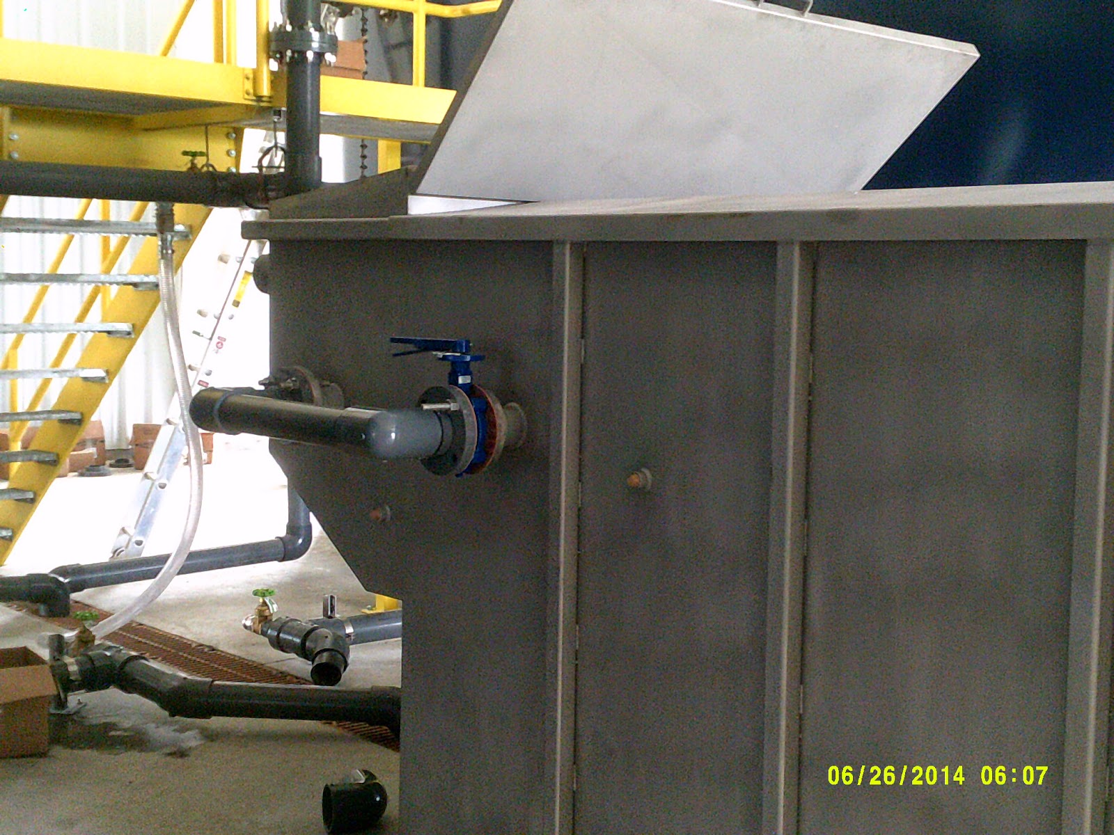
June 27. Side view of the newly installed stainless steel overflow weir/clearwell tank. This tank is placed between the filter tanks and protects the filters from being inadvertently dewatered as well as being a constant head device which maintains constant flow, adjusting for headloss in the filter. The 3" valve controls flow through the filter. A valve on the opposite side of the tank controls flow through the other filter.

June 27th. Prior to loading the sand, the gravel layers are covered with water and chlorinated to sanitize. Careful treatment of the gravel is critical to successful slow sand filter start up.

The Building goes up around the tanks, which are already loaded with gravel and have underdrain installed.

4/29 A view from the water tower showing the completed tanks with gravel and underdrains nearing completion. Next, the building will be built around the filters. When that is completed, the weir/clearwell tank, and plumbing will be completed and sand will be loaded. Getting close folks. Stay tuned!

4/22 Course gravel went in first, then the slotted underdrain pipe and connecting manifold. The gravel was washed multiple times to make sure that clean water will come out of the filter when it is started up.

4/17 Looking inside the tank with protective mastic applied and stainless steel nozzles for the inlet, outlet, harrowing, and overflow. Next- the gravel and underdrain piping going in.

4/16. here are the two filter tanks almost completed, The underdrain laterals are stacked in the foreground. Since this photo was taken, the a sealer was applied to the inside of the tanks to protect them from the gravel media. Next step will be placing course gravel in the bottom of the tank, followed by assembly of the slotted PVC underdrain piping, then the rest of the gravel layers. The brown tee shape is a drain system. Later, a stainless steel clearwell/weir tank, being fabricated, will be installed between the two filters. Stay tuned!

Why build from scratch when you can go off the shelf?
Stay tuned for more pictures!